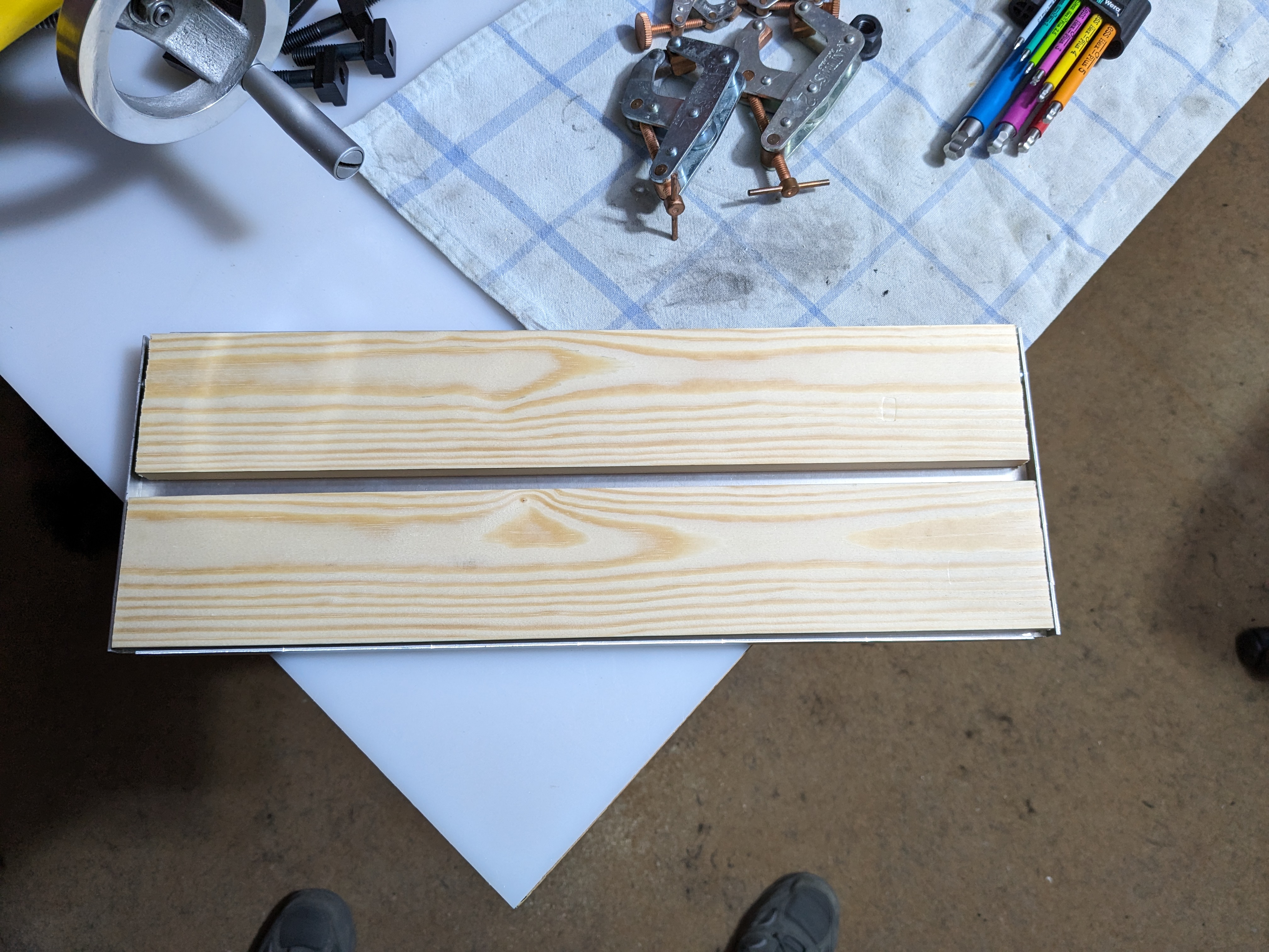
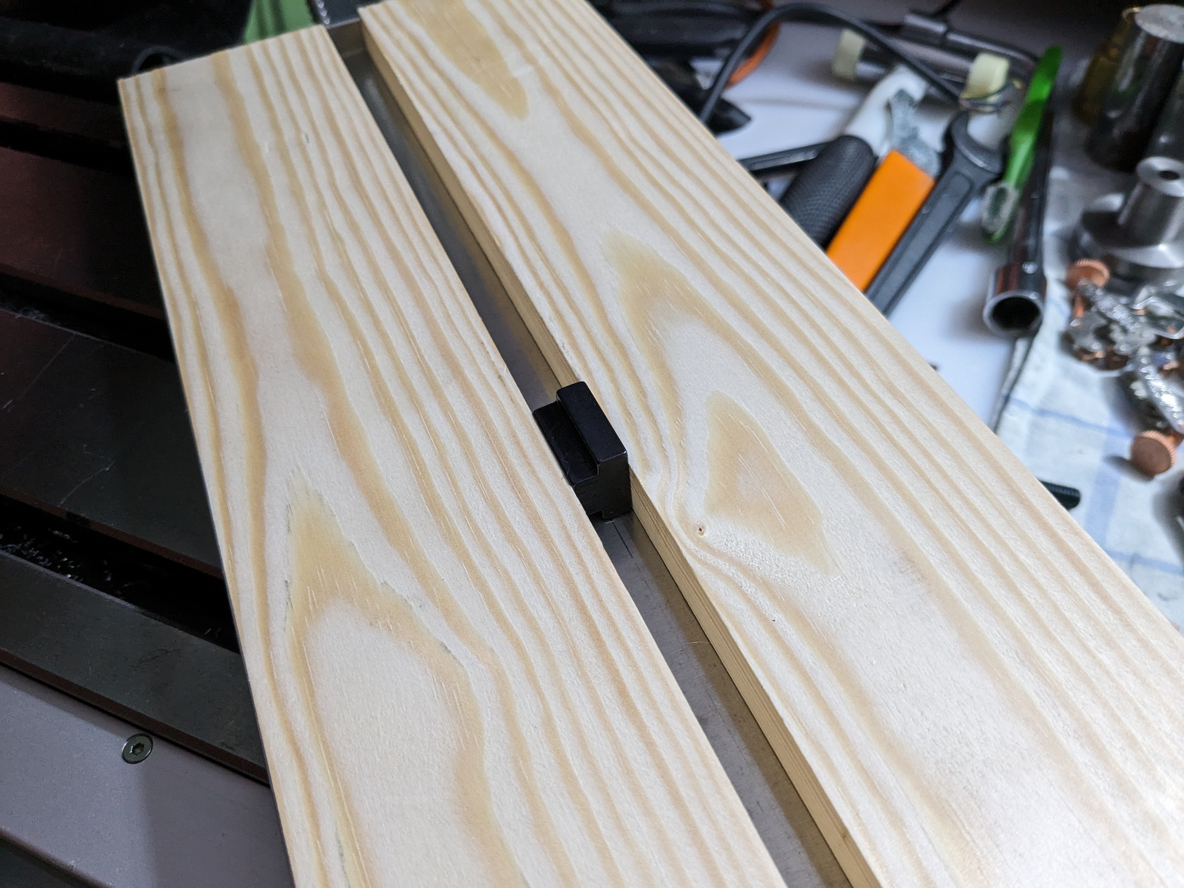
This aluminium plate goes inside the rack case and holds the main PCB. It needs only a few holes for stand-offs, so I'm using sacrificial bits of pine for setup. Again I got lucky with the dimensions turning out to be a near perfect fit.
A T-nut is just the right size to hold the wood tight.
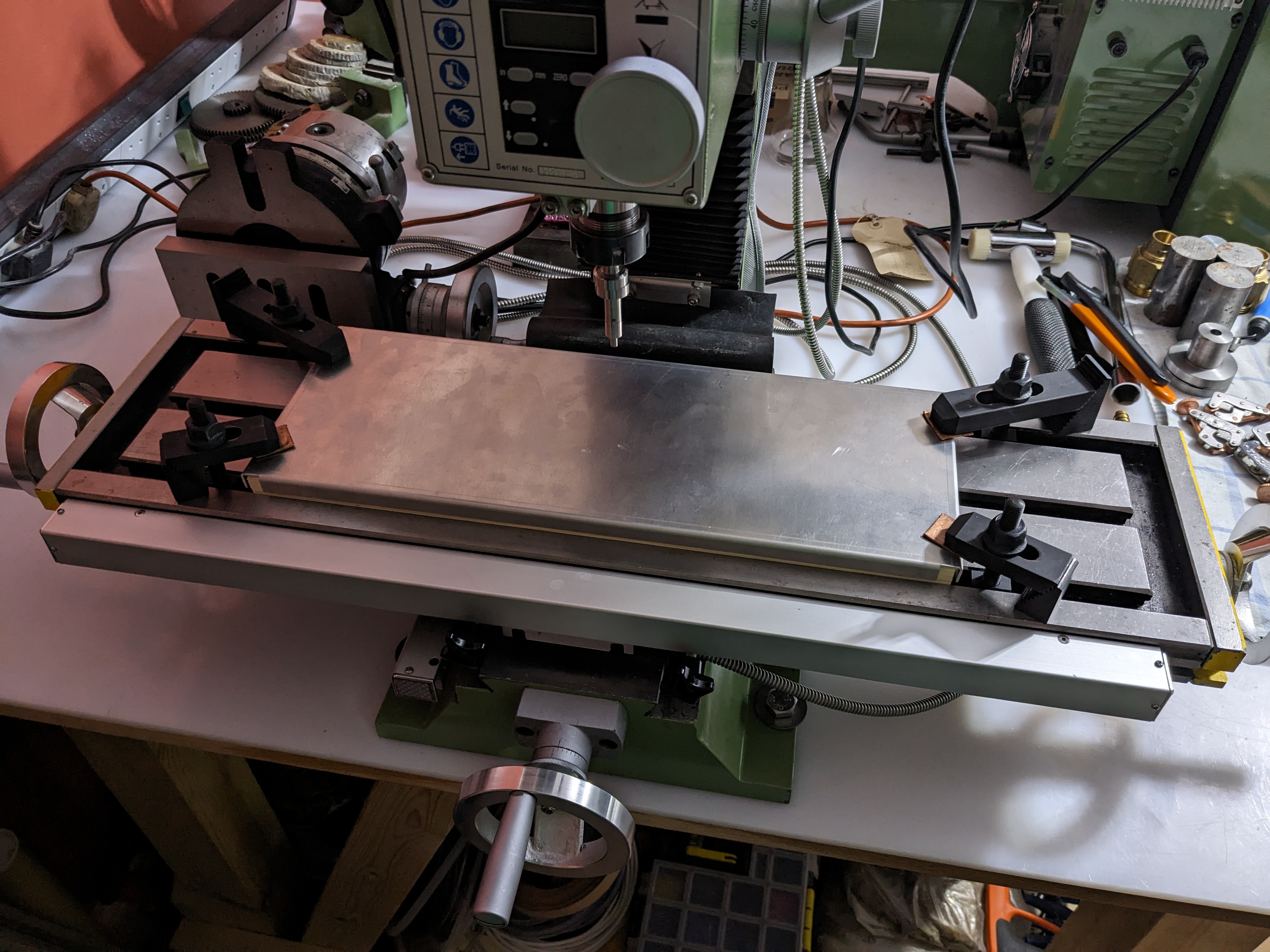
Clamped, indicated in, and centred on the DRO.
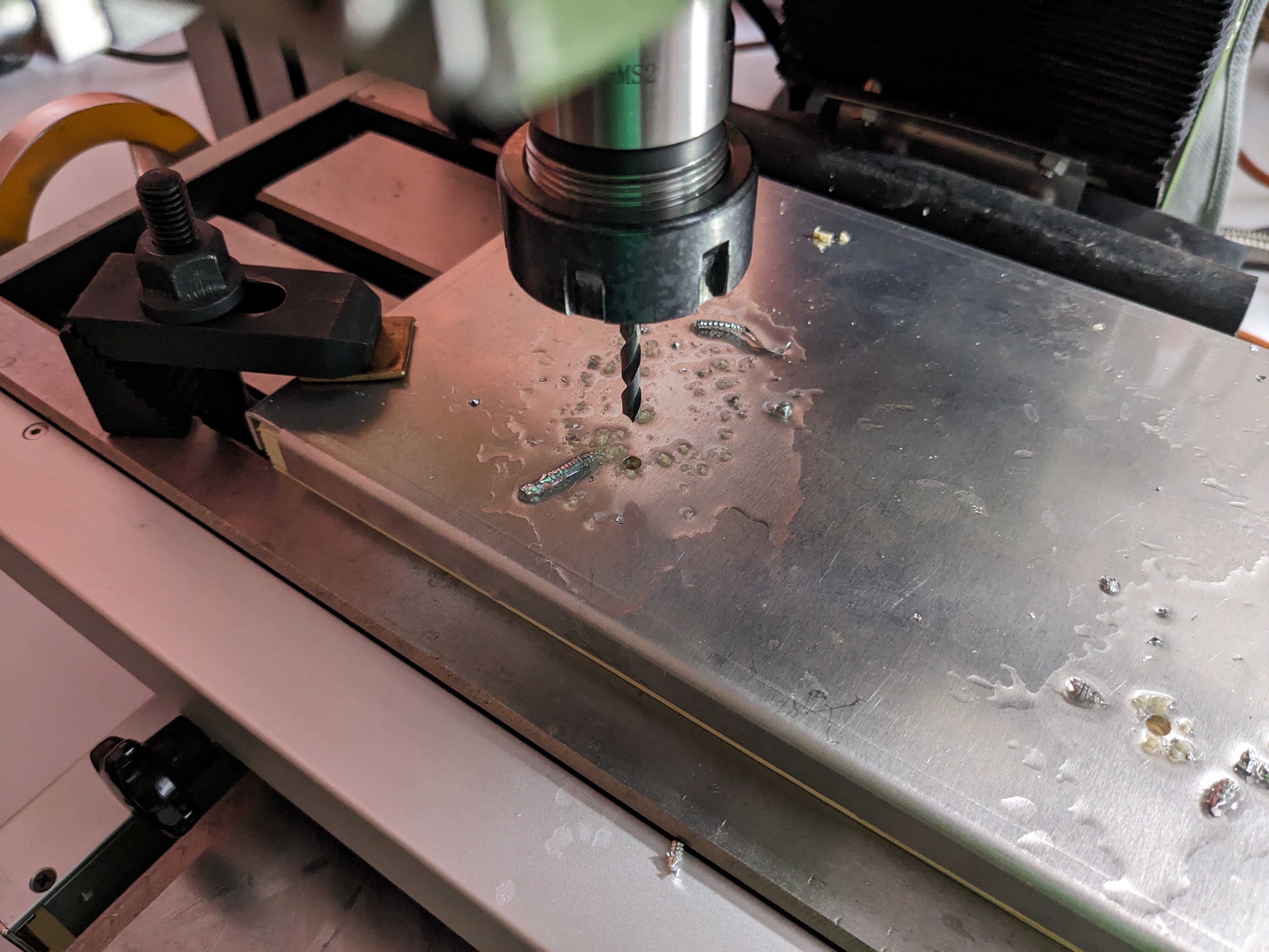
Drilling the holes, which I then reamed to the recommended size for the stand-offs.
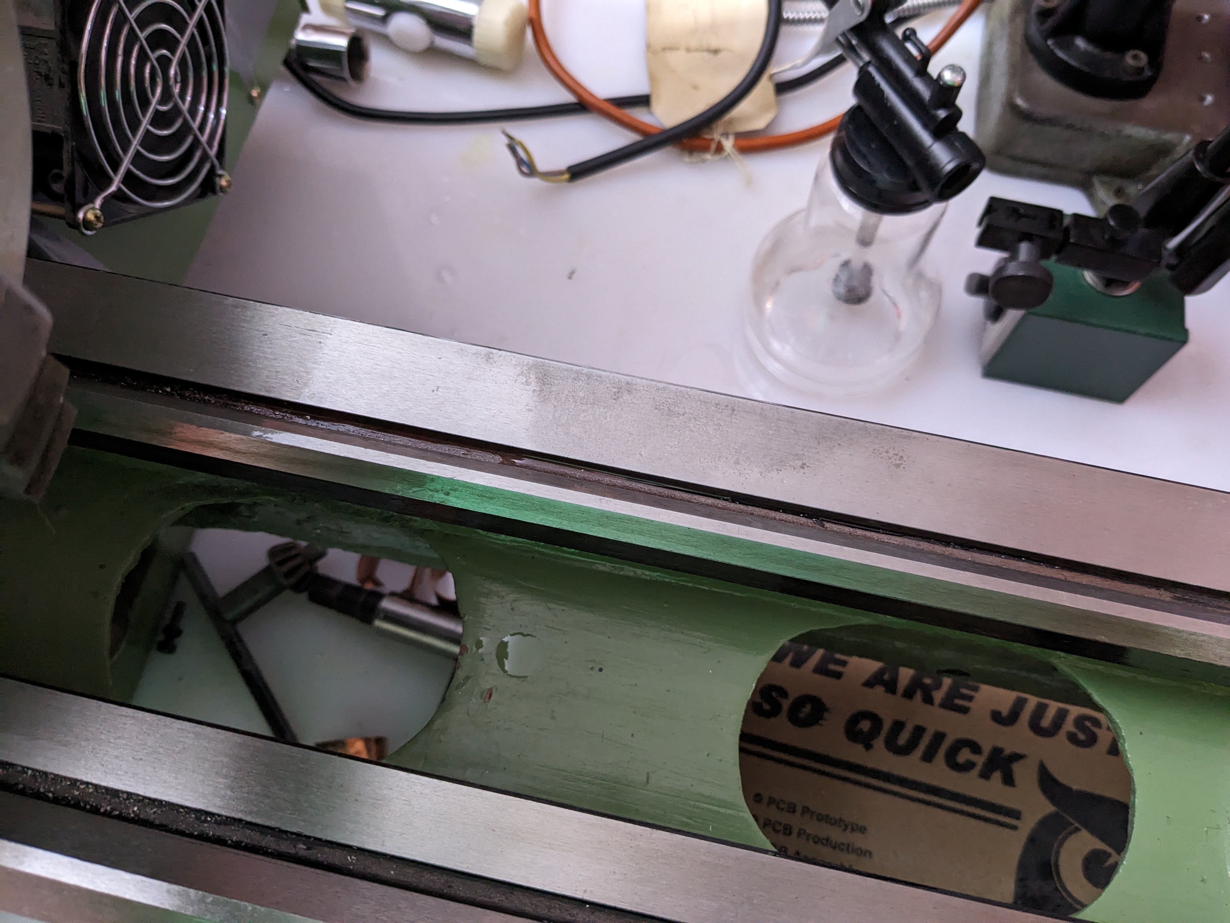
I need to make tooling to press the stand-offs into the plate, so I'll just take the cover off the lathe and...
Aargh!
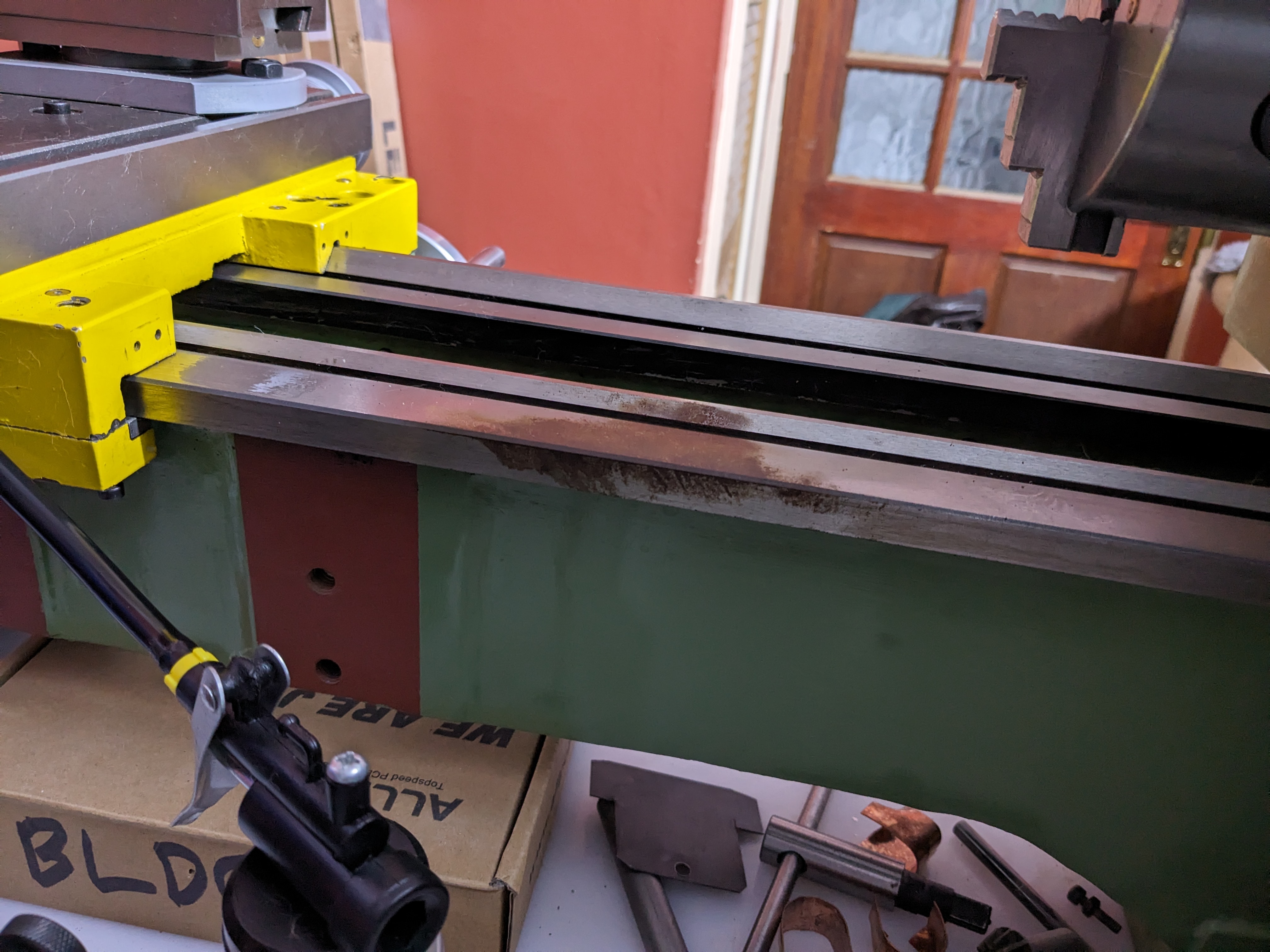
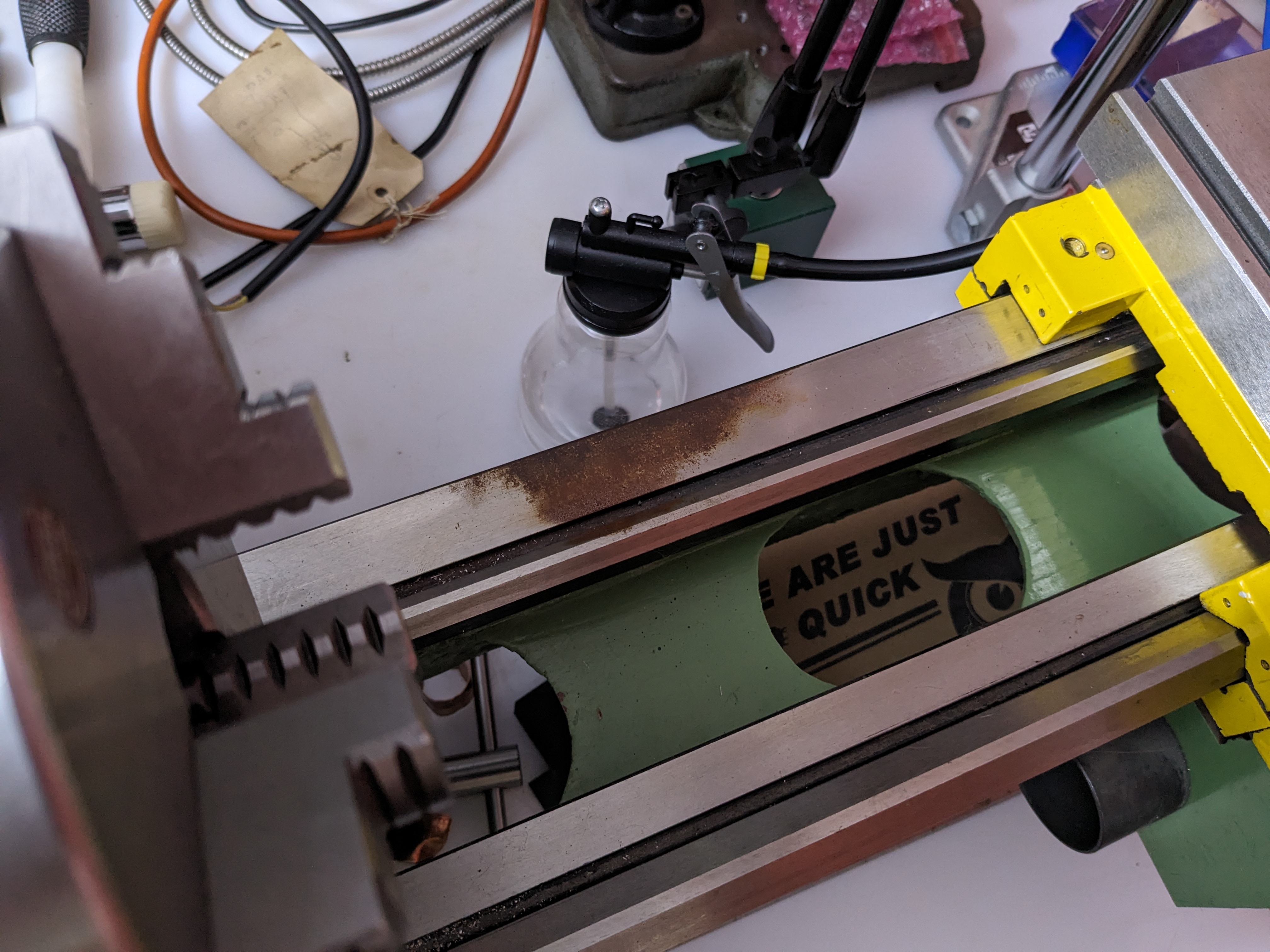
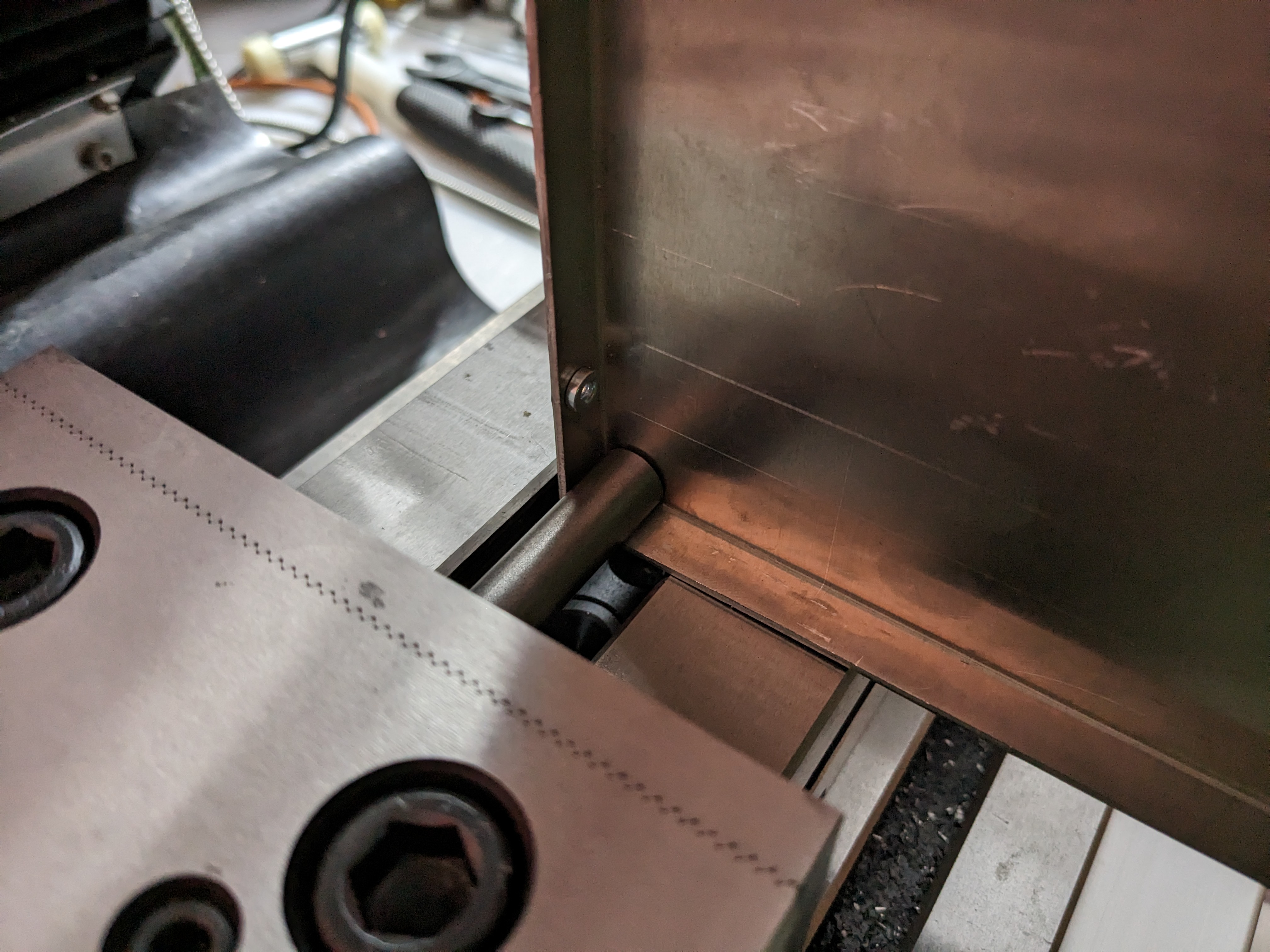
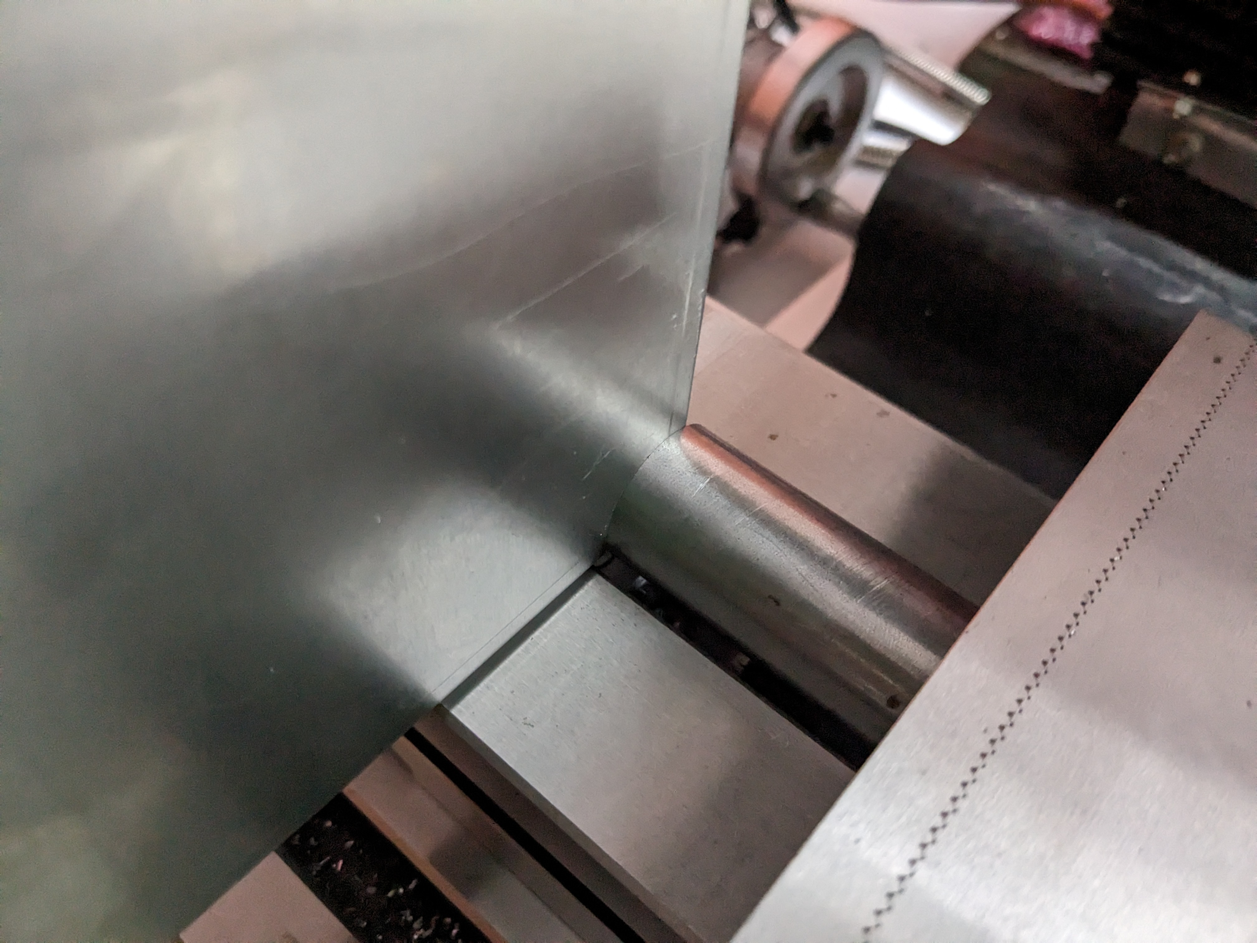
Fifteen minutes of exceedingly careful use of abrasives later. It looked worse than it was, and while I'm sure there's some damage I can't pick it up on an indicator so I think I've gotten away with it. No idea what caused it to begin with.
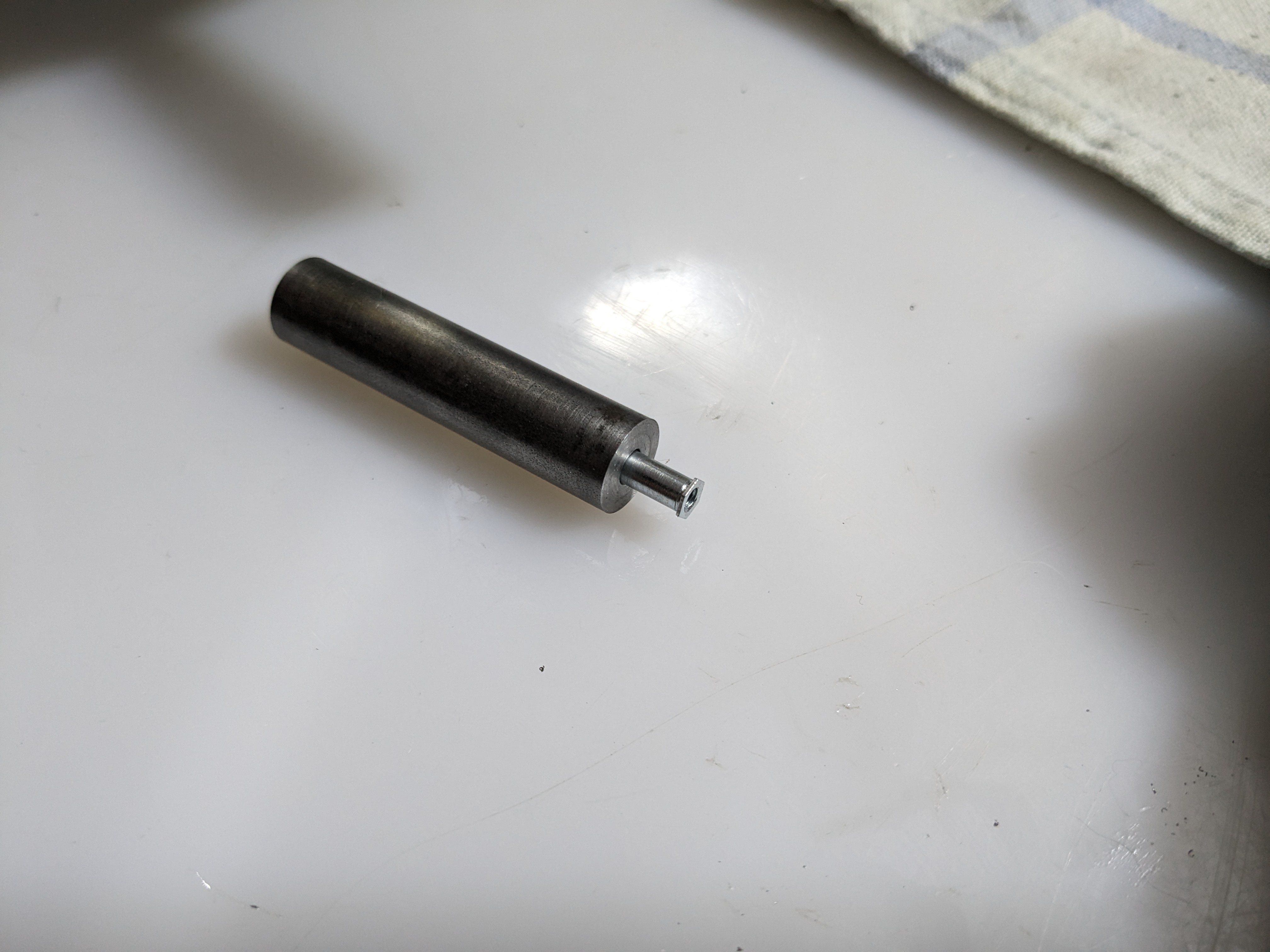
The tooling required is very simple. This piece of EN8 25mm round bar needs only faced, drilled, and reamed to make an anvil.
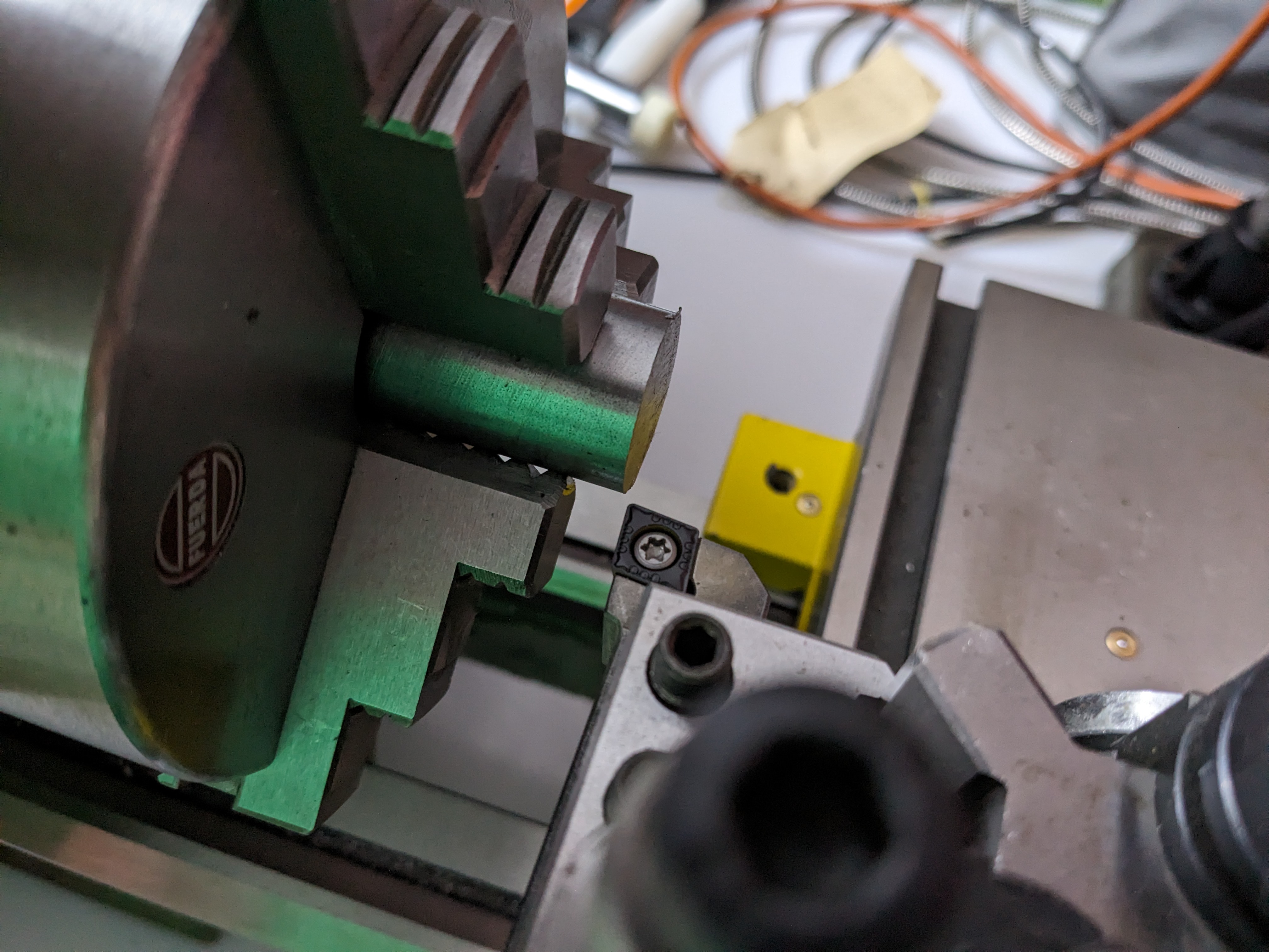
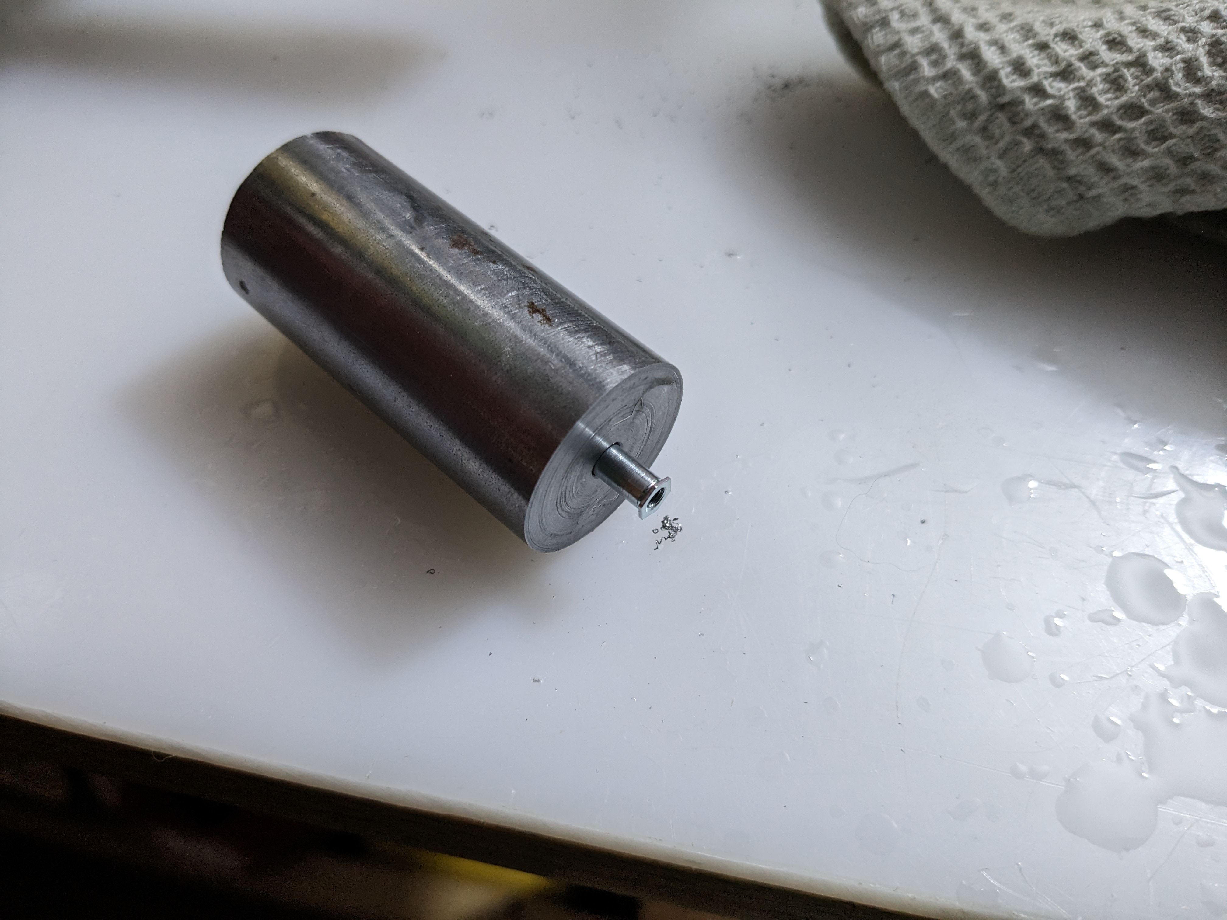
I also made one in 12mm bar, for tight corners. The other end of each bar is faced but not drilled, so each tool can be used as a punch or anvil.
I don't have a press, but the installation force is about 85% of my vice's maximum clamping force so I improvised.
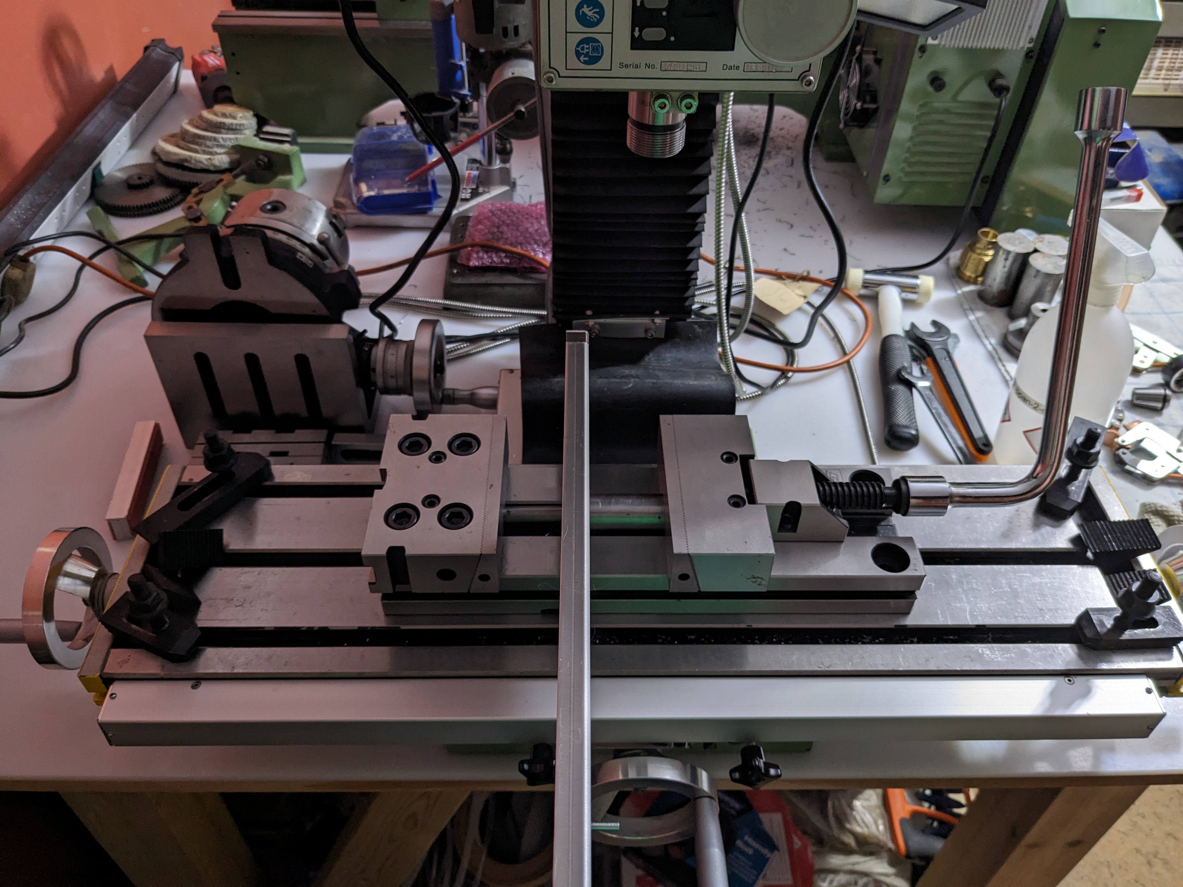
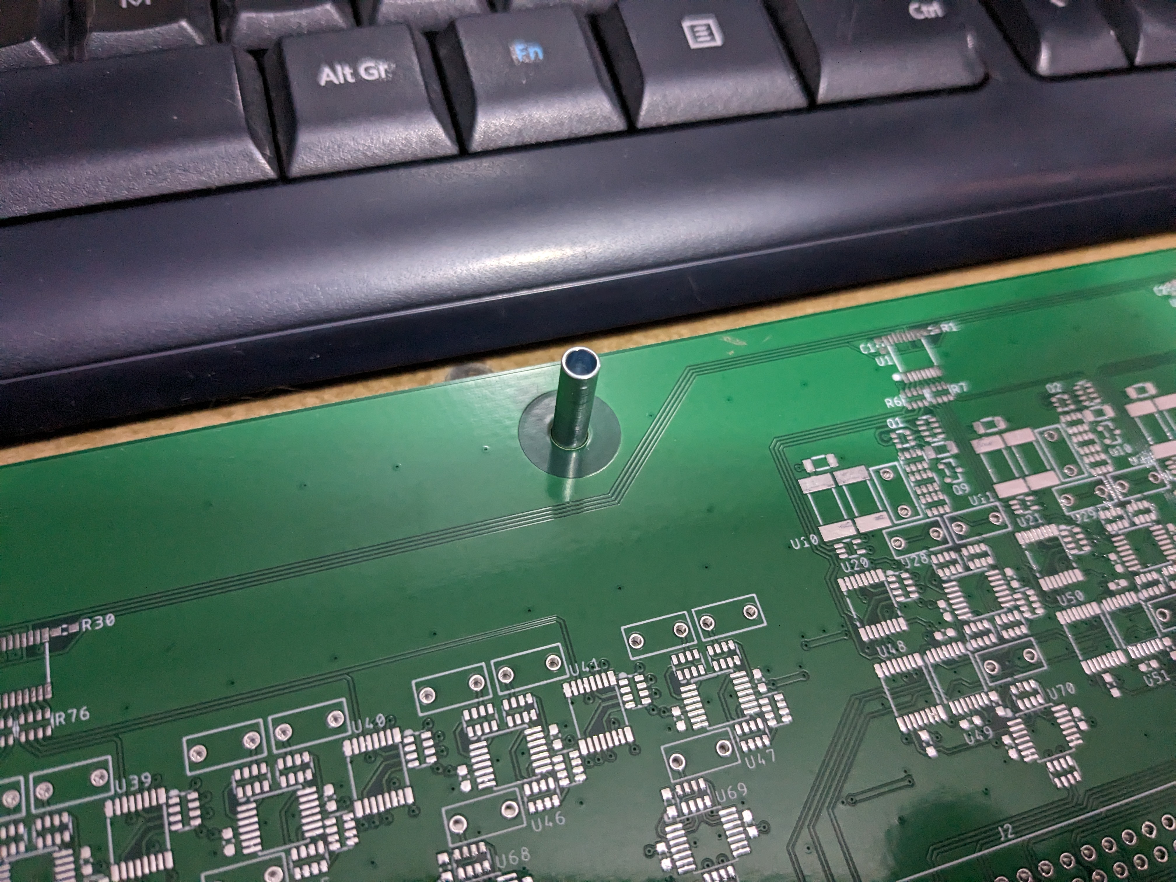
And it worked!
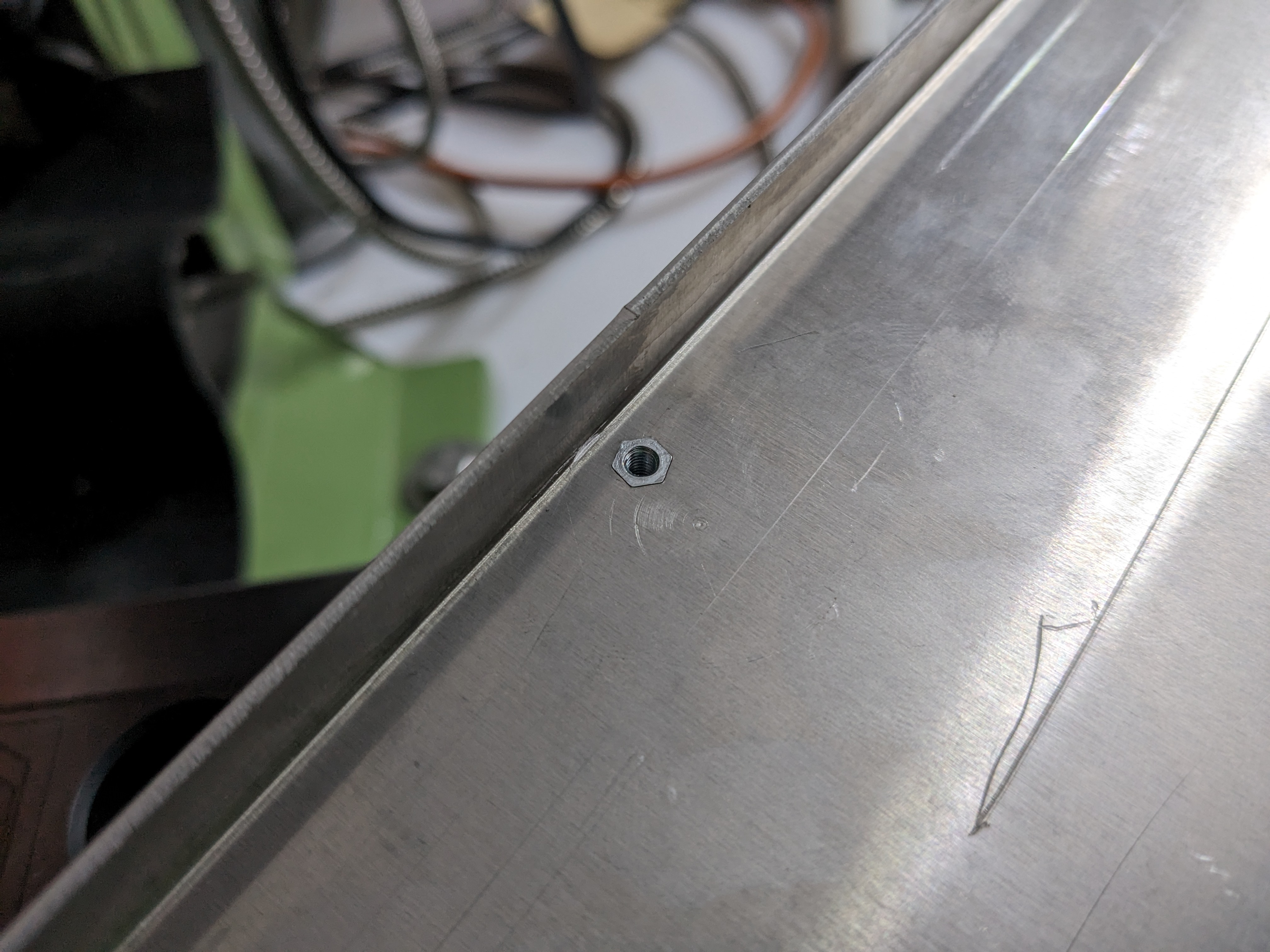
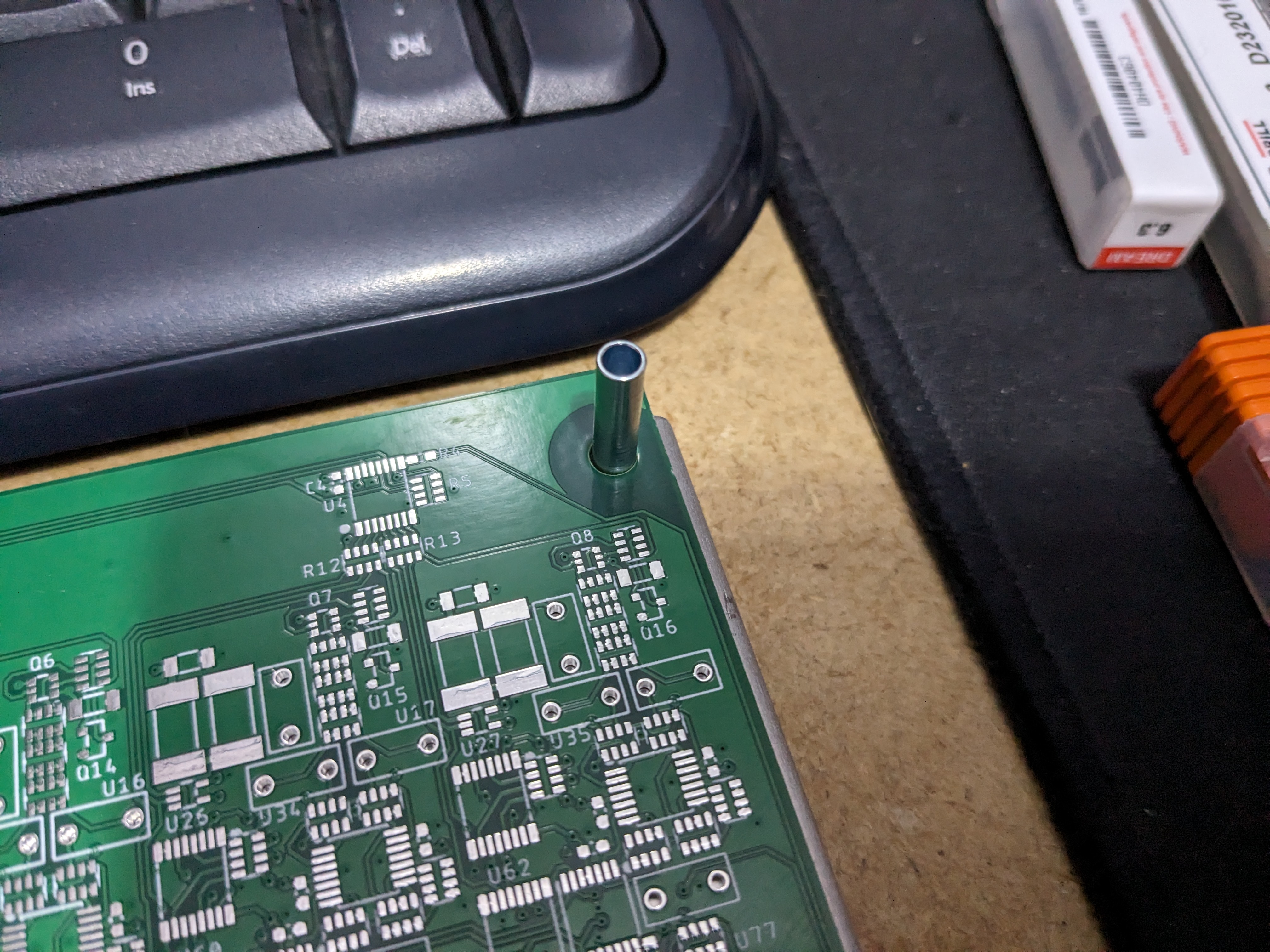
Using the smaller tool in a tight corner.
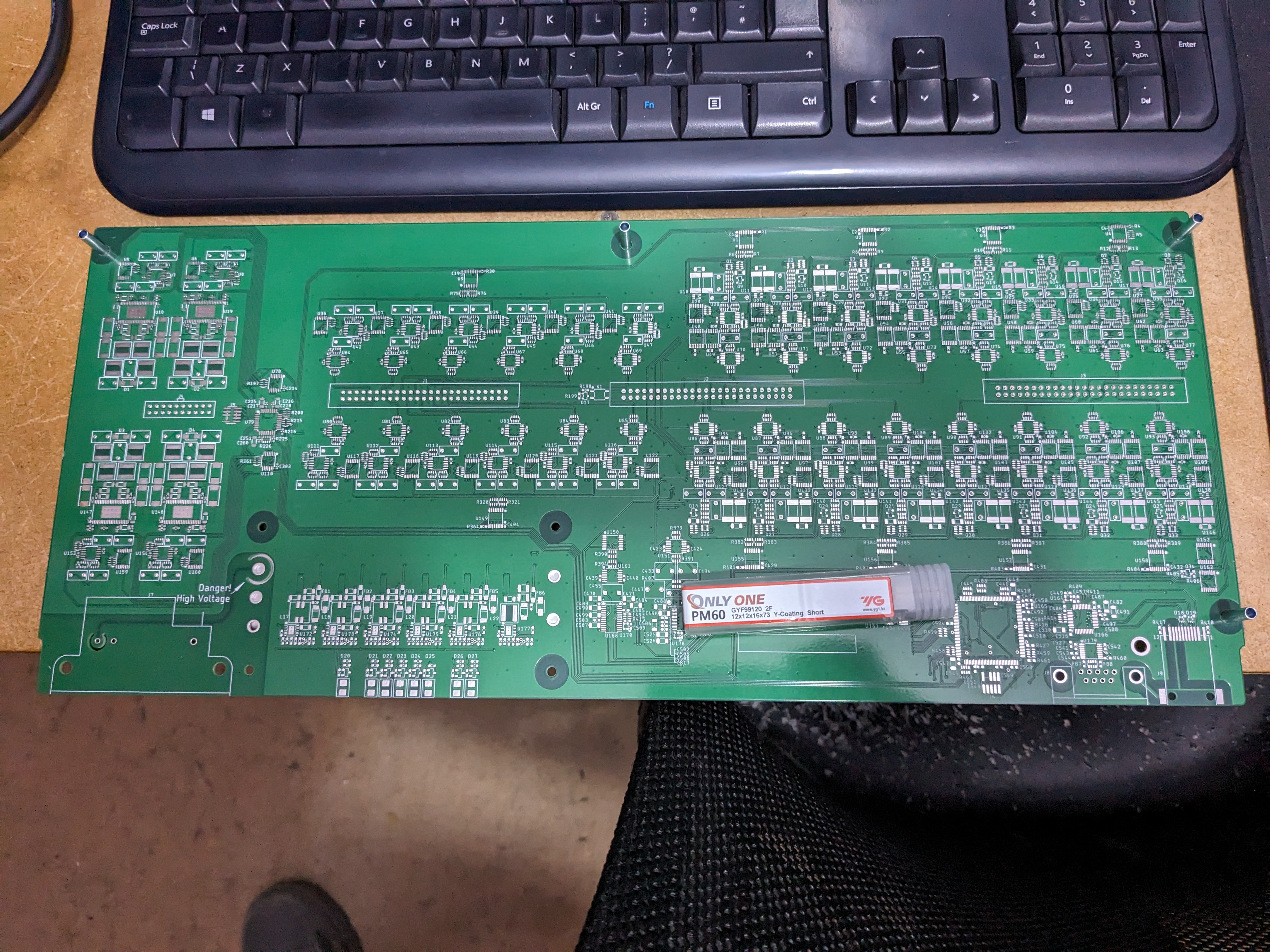
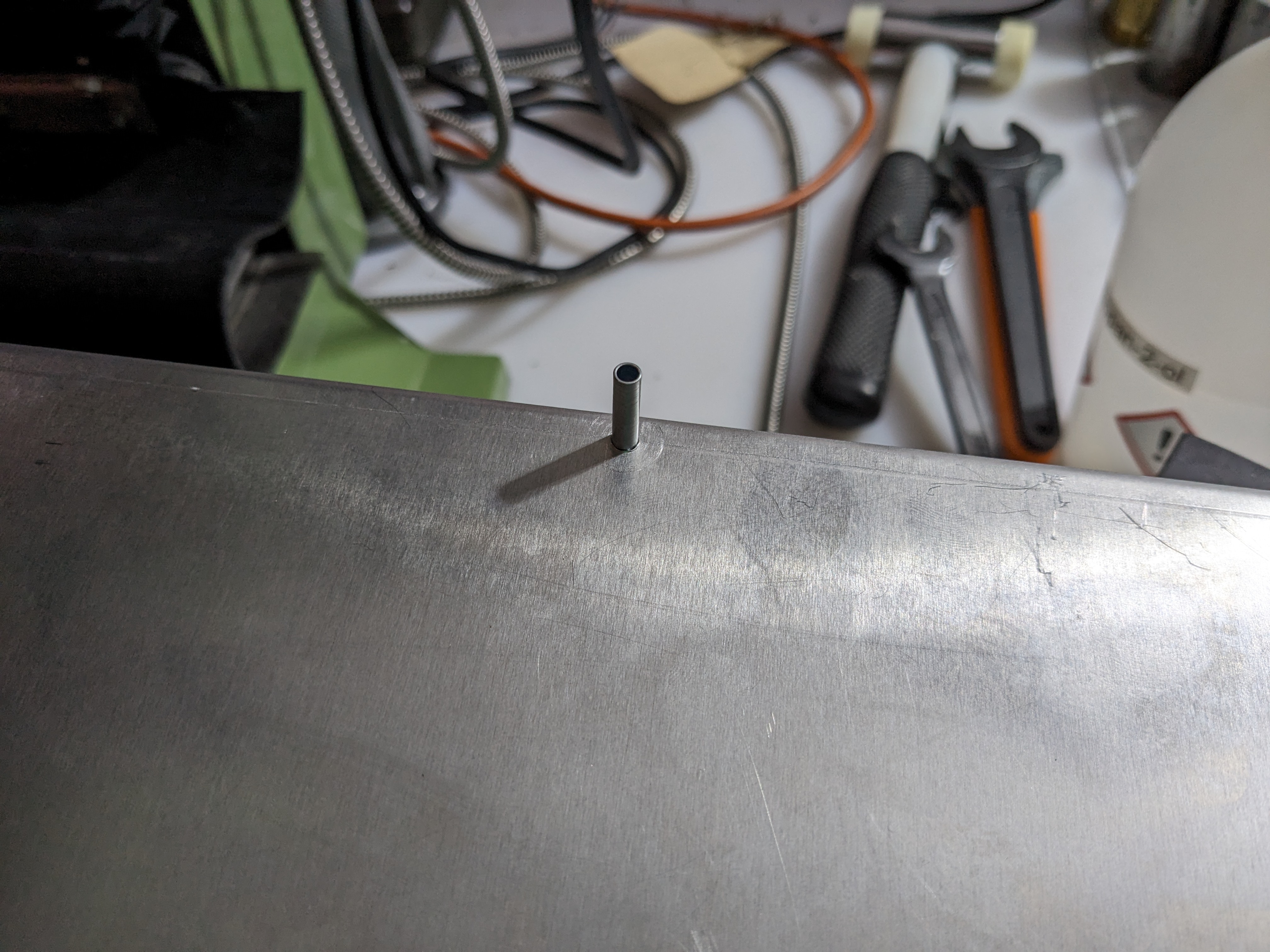
The PCB slips over the stand-offs, so they're in the correct positions. Once assembled there will be round spacers on the bottom of the PCB which sit on top of them rather than slide over them.